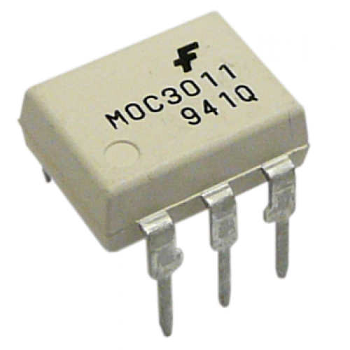
I like that it uses opto-isolators instead of mechanical relays, and I'm glad someone penciled in NTE part numbers on the drawing which helped me find suitable alternates for a few of the original parts that are obsolete and not well documented. For the optos, I went with the original part (MOC3011).

Here's the board with just the components soldered in place, before I added the interconnects, using solid core wire. The dark orange lines which I added to the picture show the paths of the interconnections. The fuse is a 4-amp Slo-Blo, which is half as tolerant (of current) as the original 8-amp fuse. So, the sustained current of the vacuum pump control circuit is below 4 amperes. Whereas, the TRIAC (which I heat-sinked, with thermal compound, but no insulator, since the package is 'isolated tab') is rated for 10 amperes, and the 24 AWG solid core wire that I used to interconnect the components on the board was twisted as a tight, tinned pair, doubling its effective diameter to the equivalent of approximately 18 AWG, which has fixture-safe 'ampacity' of over 7 amperes.
There are 620-Ohm resistors in front of the inputs of the two opto-isolators because they only need a small fraction of the 24 V coming from the lathe that the old relays needed all of. Since these isolators use infrared light to close the path under control, they technically don't use 'optical' light, since infrared wavelengths are longer than those which are visible, and only those are 'optical' wavelengths. Better to call them, 'photo isolators.'
When the lathe is turned on and the carriage is parked at the far right position on the bedways, one can play a record on the turntable without having the vacuum pump start up. However, as soon as the carriage is moved a little to the left, if one presses the turntable pushbutton (and the light bulb is working), the +24 V control signal from the lathe's power supply which was always on conductor, P-808-1, will finally be of use, since ground will now appear on conductor, P-808-3 (which was blocking the relay (or isolator) from working by also presenting +24 V, which it gets from the turntable pushbutton lamp contact, until the turntable pushbutton bulb uses it! The ground it presents to the relay / isolator appears when the turntable pushbutton lamp is on and, therefore, grounded, so it turns on the vacuum pump relay whenever the turntable is on and turns it off as soon as the turntable pushbutton is again selected to stop the turntable from revolving, since the lamp inside the pushbutton turns off when its referenced contact floats, again, at +24 V, which makes the relay /isolator receive the same voltage on both electrodes, which is a potential difference of 0 V...).
As with the relay circuit, turning on the turntable activates the normal mode of the control circuit, causing the vacuum pump to operate with attenuated speed. The pump speed (which creates the suction intensity) will, at this time, be determined by the deflection of the 250-kOhm potentiometer (Allen-Bradley Mod Pot), mounted on the outside of the Lee chip pump box.
When the cutting head yoke is lowered, either by manually selecting the 'Drop' pushbutton, or by allowing the yoke to lower on its own, during an automated cut, the General Logic board in the lathe's card cage causes ground, temporarily, also to appear on conductor, P-808-5. This activates isolator, A2, which, through its own internal infrared light signal, closes the load contacts, causing the vacuum pump control to present the full mains power to the pump for a brief interval, determined by a 555 timer circuit, timed sufficiently to establish good suction of the chip when the stylus first enters the lacquer, and which then automatically removes ground from that conductor de-activating the internal l.e.d. of isolator, A2, and isolator, A1, remains activated, resuming normal mode control of the pump.
Although I can use a Variac to change pump speed manually, it's better to have this happen automatically, since there are other things to focus on when the cut begins. The lathe has been running well since the restoration mostly concluded in 2014, serving up master cuts for many pressings, but 2019 was the year for restoring the last feature to be restored - automated 'vacuum pump' control. The control signal contacts are relatively far from the mains line contacts on the board, and I encapsulated the control signal contacts with Liquid Tape to protect them from being touched by outside voltage sources. Furthermore, I now have added crow-bar protection to the sensitive logic chips' regulated supply. I may end up mounting the board in an enclosure. For now, at least it's outside of the pump box, on threaded stand-offs, mounted to a panel from a disused Neumann SP console Kassettenmodul which happened to fit the footprint of the board. (I have additional parts to make another Hi/Lo 'vacuum pump' control circuit board for #660. For now, it has its own Variac on its Lee pump and doesn't really need any suction, since it is only being used for auditioning 14" mothers and to test mods at this time.)